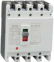
1. Application
HM1 DC series DC moulded case circuit breaker is developed by advanced design and manu�facturing technology, suitable for a the circuit of AC50/60Hz, rated voltage is DC250V, DC500V, DC750V and DC 1000V, rated purrent up to 400A, the circuit breaker have function of short circuit, overload and under-voltage protection to protect circuit and power equipment against damage. The breaker are comply with the IEC60947-1 and IEC60947-2.
2. Main Technical Specifications
| Type | HM1 DC-125 | HM1 DC-250 | HM1 DC-400 |
| Frame current Inm(A) | 125 | 250 | 400 |
| Rated current In (A) | 10,16,20,25,32,40,50,63,80,100,125 | 125, 140,160,180,200, 225,250 | 250,315350,400 |
| Pole number | 1 | 2 | 3 | 4 | 1 | 2 | 3 | 4 | 3 | 4 |
| Rated insulation voltage Ui (V) | 100C |
|
| Rated impulse withstanding voltage Uimp(V) | 8000 |
| Rated working voltage Ue(V) | DC250 | DC500 | DC750 | DC1000 | DC250 | DC500 | DC750 | DC1000 | DC 750V 1000V | DC1000V1500V |
| Using category | A |
| Isolation | o |
| Arcing distance (mm) | W50 | W100 |
| Rated short time making capacity Icm (kA) | 100% leu |
| Rated limiting short- circuit breaking capacity leu (kA) | DC250V | 35 |
|
|
| 35 |
|
|
|
|
|
| DC500V |
| 35 |
|
|
| 35 |
|
|
|
|
| DC750V |
|
| 20 |
|
|
| 20 |
| 50 |
|
| DC1000V |
|
|
| 15 |
|
|
| 15 | 35 | 35 |
| DC1500V |
|
|
|
|
|
|
|
|
| 25 |
| Rated service short-circuit breaking capacity les (kA) | 75% leu |
| Electrical life (times) | 2000 | 2000 | 1000 |
| Mechanical life(times) | Withoutmaintenance | 10000 | 10000 | 5000 |
| Withmaintenance | 20000 | 20000 | 10000 |
| Shunt release | AC230V 400VDC24V-30VDC220V-250V |
| Under-voltage release | DC220-250V |
| Auxiliary contact | AC-15:AC400/0.3ADC-13:DC250V/0.15A |
| Alarm contact | AC-15:AC400/0.3ADC-13:DC250V/0.15A |
| Motor-driven operation | AC110V 230V 400V |
| device | DC24V-30V, DC110V-125V, DC220V-250V |
3. Wiring diagram

Power system suitable for above wiring diagram
| Rated working voltage | Power/Load wiring type |
| Ungrounding system | Negative pole grounding system | Core point grounding system |
| DC250V | C |
| - | D |
|
| C |
| DC500V | E | - | D | E | - | - | C |
| DC750V | E | H | E | F | G | I | H |
| DC1000V | - | H | - | - | G | I | H |
4. Application in DC Grounding system
| System catelogy | Grounding system | No grounding system |
| Negative pole grounding | Core point grounding |
| All of fault category |
|
|
|
| Fault effect | Fault I | Producing the highest short-circuil currentBreaking the positive pole contact connected to power | U/Svoltage.producing the highest short-drcuil current effect Breaking the positive pole contact connected to power | No effect |
| Fault II | Producing the highest short-€ircuil current But the contaets in series are all breaking | Producing the highest short-circuil current But the contaets in series are all breaking | Producing the highest short-circuil current But the contaets in series are all breaking |
| Fault III | No effect | the same as fault I, but breaking the negative pole contact connected to power | No effect |
| The most serious condition | Fault I | Fault I and fault III | Fault II |
| Breaking pole condition | Can be in series on the positive pole, breaking both poles | With U/2, use breaking highest short-circuit current to each pole | Breaking both poles |
| Wiring conduct selection |
| Rated current(A) | Section area (mm2) | Rated current(A) | Section area (mm2) |
| 16, 20 | 2.5 | 125, 140 | 50 |
| 25 | 4 | 160 | 70 |
| 32 | 6 | 180, 200, 225 | 95 |
| 40, 50 | 10 | 250 | 120 |
| 63 | 16 | 315, 350 | 185 |
| 80 | 25 | 400 | 240 |
| 100 | 35 |
|
|
5. Outline and Installation Dimension(mm)